INDUSTRIAL ROBOTICS for III - II MECH JNTUK (R16) UNIT - II
UNIT - II: Components of the Industrial Robotics
Main components of an Industrial Robot:
A typical stand-alone robot shown in the figure below comprises of the following basic components, namely.- Manipulator (Mechanical Arm)
- Sensors devices (Feedback Components)
- Robot Tooling (End-effector)
- Robot controller unit (RCU)
 |
| Basic components of an Industrial Robot and Their Connectivity. |
Manipulator:
It consists of base, arm, & wrist similar to a human arm. It also includes power source either electric, hydraulic or pneumatic on receiving signals from robot controller this mechanical unit will be activated. The movement of the manipulator can be in relation to its coordinate system. Which may be Cartesian, Cylindrical. etc.
Depending on the controller, the movement may be a point to point motion or continuous motion.
The manipulator is composed of 3 divisions,
- The major linkages
- The minor linkages (wrist components)
- The end effectors (gripper or tool)
Sensors devices:
These elements inform the robot controller about the status of the manipulator. These sensors can be either analog or digital and combination.
The sensors may be
- Visual
- Non – Visual
- Contact
- Non- Contact, or
- Any combinations of above-mentioned types
Robot Tooling:
Robot tooling is the component that executes the required work of the robot and is also called as the end effector. It is provided at the end of the arm. Its design depends on the nature of the work to be performed by the robot.
The Robot End-effector may be,
- A Hand or a Gripper or a Holding Device
- A Tool
Robot controller unit (RCU):
The instructions to the robot to perform the desired tasks are given as an input through the keyboard of this unit. The controller converts the input programs to suitable signals which activate the manipulator to perform the desired tasks.
Types of robot arms OR function line diagram representation of robot arms:
The arms of the robot classified as following:
1. Cartesian robot:
The Cartesian robot has the simplest configuration with prismatic joints. The work envelope of a Cartesian robot is cuboidal. It has large work volume but low density. It consists of 3 linear axes.
2. Cylinder robot:
Cylinder robot makes use of two perpendicular prismatic joint and one revolute joint. The work envelope of cylinder robot approximates to a cylinder. It consists of one linear and one rotary motion.
3. Polar robot(Spherical):
The Polar robot consists of a rotating base, a telescopic link which can be raised or lowered about a horizontal revolute joint. It has a work envelope of a partial spherical shell. It consists of one linear and two rotary axes.
4. Joint arm (Articulated arm):
Joint arm robot is also known as an anthropomorphic robot. It functions similar to the human arm. It consists of two straight links. Similar to the human forearm and upper arm. These two links are mounted on a rotary table and have a work envelope of spherical shape. It is the most dexterous one since all the joints are revolute joints. It consists of 3 rotary axes.

The Four Common types of arm configurations and their work envelopes
Degrees of Freedom:
The number of independent motions or movement that an object can perform in its workspace is known as a Degree of Freedom of the object.
or
The number of independent variables required to define the position and orientation of a body in its workspace is known as Degree of Freedom of the body.
 |
| 3 DOF Motions |
A rigid body free to move on a plane has got 3 - degrees of freedom. i.e., 2 translations and 1 revolution about the normal to the plane of motion. This kind of manipulator with 3 degrees of freedom is known as a planar manipulator.
 |
| 6 DOF Motions |
A rigid body free to move in space has got 6 - degrees of freedom. i.e., 3 translations and 3 revolutions. A manipulator with 6 degrees of freedom is known as a spatial manipulator.
However, there are many manipulators that do not have full 6 degrees of freedom. Since not all tasks require 6 degrees of freedom.
Calculation of Degree of Freedom for a Manipulator:
The degree of freedom of a manipulator is the number of independent motions possessed by that manipulator in its working space. The independent motions depend on the number and type of links and joints in that manipulator. The Degree of Freedom of the joints decides the DoF of the manipulator.
The relation between the Number of Degree of Freedom can be given by the Kutzbach Criterion. And is as follows:

N = No of Individual Motions in the Manipulator or Degrees of Freedom
m = Maximum number of Degrees of Freedom of a free body in the Workspace
3 for Planar Manipulator
6 for Spatial Manipulator
n = Total number of links in the Manipulator
ji = Number of joints having 'i' number of DoF restrictions or having (m - i) DoF
- The DOF is equal to the number of links in an open kinematic chain.
- Robot with 6 DOF is called as a spatial manipulator (arm, body &wrist)
- Robot is more than 6 DOF is called as a redundant manipulator.
Different types of joints are used in robots:
The different types of joint are used in robots are,
- Prismatic Joint (Linear Motion)
- Revolute Joint (Revolution Motion)
- Rotational Joint (Rotational Motion)
- Twisting Joint
- Screw Joint (Linear and Rotational Motion)
- Spherical Joint
- Planar Joint
- Cylindrical Joint
1. Prismatic Joint (Linear Motion):
Prismatic joints are also called sliders, constituting purely linear motion along the joint axis. The joint may be of two types depending on the construction as shown in the figure a linear joint and an orthogonal joint. This type of motion is common in hydraulic or pneumatic cylinders, there is no rotation.
The degree of freedom is one (i.e., translation).
2. Revolute Joint (Revolution Motion):
Revolute joints constitute purely revolution motion about the joint axis. Revolute joints are most commonly found in industrial robots. There is no translation motion. Most revolute joints cannot rotate through a full 360 degrees but are mechanically constrained.
The degree of freedom is one. (i.e. Revolution)

3. Rotational Joint (Rotational Motion):
Rotational joints are often called Pivot joints or Pin joints due to their mechanical construction. In this Joint, the two adjacent links are connected by means of a pin. This joint allows pure rotation motion between the links about the pin joint axis.
The degree of freedom is one. (i.e. Rotation)

4. Twisting Joint:
It is another variant of the rotary joint, where the two adjacent links remain aligned along a straight line but one turns (twists) about other around the link axis.
The degree of freedom is one. (i.e. Twisting)

5. Screw Joint (Linear and Rotational Motion):
Screw joints are a combination of the first two types of joints. They constitute a simultaneous rotation and linear motion along a joint axis. Screw joints are more often used in tools for a robot end effector rather than a joint of motion for a robot. This joint follows the thread of the axis to move along the axis.
The degree of freedom is two. (i.e. Translation and Rotation)
6. Cylindrical Joint:
Cylindrical joints are a combination of prismatic and revolute joints. The motion in the joint may be translation, revolution or combined.
The degree of freedom is two. (i.e. Translation and Rotation)

7. Spherical Joint:
Spherical joints are most utilized joints and just slide causing a revolving movement.The degree of freedom is three. (Three rotations)

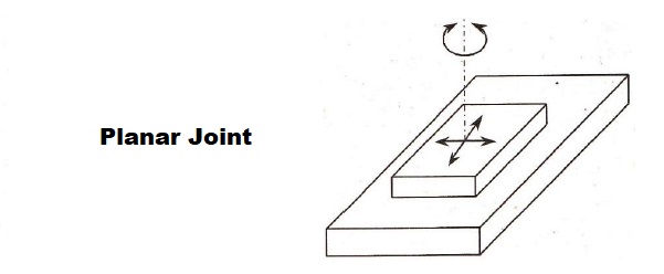
8. Planar Joint:
In this type of joint one surface freely moves over another surface. The relative motion between them consists of sliding and rotation about the plane normal.
The degree of freedom is three as the figure. (i.e., one rotary and two sliding motions)

End effector:
In robotics, the physical construction of the robot consists of a body, arm, and wrist of the machine. The body is attached to the base and arm assembly attached to the body. At the end of the arm, a wrist is attached, which consists a number of components to allow variety position. Relative motion between body, arm, and wrist are provided by joints. The joint motions are either rotating or sliding. The body, arm, and wrist assembly are also called as a manipulator. Attached to the robot wrist is a hand (End effector). The end effector is not considered as part of the robot. The arm and the body joints keep the end effector in It is also called Gripper.
Types of End- Effectors:
End- Effectors are categorized into two types,
- Grippers
- Tools
1. Grippers:
Grippers would be utilized to grasp an object, usually the work part and hold it during the robot work
cycle. The types of material used for grippers depends on the orientation of part & friction between parts & grippers. The applications include material handling, machine loading, unloading, palletizing and other similar operations.
The operations performed by grippers are
- To move the fingers with commanded speeds.
- To gripper handled part with not more than specified force.
- To open, move & also the fingers at specified positions.
- To measure the dimension of a part.
Grippers are further classified as,
- Mechanical grippers
- Magnetized grippers
- Suctions or vacuum cups
- Hooks
- Scopes or ladles
Mechanical grippers:
Mechanical gripper in an end effector, that uses mechanical fingers actuated by a mechanism to grasp an object. The fingers are either attached to the mechanism.
- The function of the gripper mechanism is to translate some form of power input into the grasping action.
- The power input is supplied from the robot and can be pneumatic, hydraulic, and electrical.
- The mechanism must be able to open and close the fingers
Magnetized grippers:
Magnetic grippers are be divided into 2 types:
i. Electromagnetic
ii. Permanent magnetic.
Electromagnetic:
Electromagnetic grippers include a controller unit and a DC power for handling the materials. This type of grippers is easy to control and very effective in releasing the part at the end of the operation than the permanent magnets. If the work part gripped is to be released, the polarity level is minimized by the controller unit before the electromagnet is turned off.
Permanent magnetic:
The permanent magnets do not require any sort of external power as like the electromagnets for handling the materials. After this gripper grasps a workpart, an additional device called as stripper push – off pin will be required to separate the workpart from the magnet. This device is incorporated at the sides of the gripper.
- This gripper only requires one surface to grasp the materials.
- The grasping of materials is done very quickly.
- It does not require separate designs for handling different size of materials.
- It is capable of grasping materials with holes, which is unfeasible in the vacuum grippers.
Suctions or vacuum cups:
It is used to left the flat glass of the work. This type of gripper is typically made of elastic material such as rubber, soft plastic. The shape of the vacuum is shown in figure Commonly used round type. It means of removing the air between the up and part surface to create the vacuum tin required the vacuum pump & venture in of common devices and for those purposes.
The lift capacity of suction cup depends upon the effective area of the cup. The negative air pressure between the cup & the object.
F = P * A
Where,
F = force,
P = negative pressure,
A = total effective area of the suction cup used to create the vacuum.
Hooks gripper:
Hooks can be used as end effectors to handle containers of parts to load and unload parts, hanging from, power head conveyors. The items to be handled by a hook must have some soft handle to enable the hook to hold it.
Scopes or ladles:
Scopes or ladles can be used to handle certain materials in liquid or powder form, chemically in liquid or powder form, good materials etc. that can be handled by a robot using method of handling.
Types of Mechanical gripper actuation:
There are various ways of classifying mechanical grippers and their actuating mechanisms. One method is according to the type of finger movement used by the gripper. In this classification, the grippers can actuate the opening and closing of the Rogers by one of the following motions:
1. Pivoting movement
2. Linear or translational movement
1. Pivoting Movement
In the pivoting movement. The fingers rotate about fixed pivot points on the gripper to open and close. The motion is usually accomplished by some kind of linkage mechanism.
In the linear movement, the Fingers open and close by moving in parallel to each other. This is accomplished by means of guide rails so that each finger base slides along a guide rail during actuation. The translational finger movement might also be accomplished by means of a linkage which would maintain them in a parallel orientation to each other during actuation.
Mechanical grippers can also be classed according to the type of kinematic device used to actuate the Roger movement. In this classification we have the following types:
i. Linkage Actuation,
ii. Gear & Rack Actuation,
iii. Cam Actuation,
iv. Screw Actuation,
v. Rope & Pulley Actuation.
i. Linkage Actuation:
The linkage category covers a wide range of design possibilities to actuate the opening and closing of the gripper. The design of the linkage determines how the input force ′𝐹𝑎′ to the gripper is converted into the gripping force’ 𝐹𝑔′ applied by the fingers. The 'linkage configuration also determines other operational features such as how wide the gripper fingers will open and how quickly the gripper will actuate.
ii. Gear & Rack Actuation:
These are some other mechanism that would provide linear motion, movement of the rack would drive to partial pinion gears and these would, in turn, open and close the finger.
iii. Cam Actuation:
The cam actuated gripper Includes a vanity possible designs, one of which is shown in Fig. cam and follower arrangement, often using & spring-loaded follower can provide the opening and closing action of the gripper. For example, movement of the cam in one direction would force the gripper to open. while movement of the cam in the opposite direction would cause the spring to force the gripper to close. The advantage of this arrangement is that the spring action would accommodate different sized parts. This might be desirable, for example, in a machining operation where a single gripper is used to handle the raw work part and the finished part. The finished part might be significantly smaller after machining.
iv. Screw Actuation:
The screw is turned by a motor. Usually accompanied by a speed reduction mechanism. When the screw is rotated in one direction, this causes a threaded block to be translated in one direction. When the screw is rotated in the opposite direction. The threaded block moves in the opposite direction. The threaded block is, in turn, connected to the gripper Buyers to cause the corresponding opening and closing action.
v. Rope & Pulley Actuation:
Rope& pulley actuating can be designed to open & closing a mechanical gripper.
Construction the path in the grippers:-
There are two ways of construction the path in the gripper.
(i) Physical construction of the path within the finger.
(ii) Holding the path by friction between the finger and the work path.
(i) Physical type:
In this approach, the gripper fingers enclose the part to some extent, thereby constraining the surface of the fingers to be in the approximate shape of the part geometry.
(ii) Holding Method:
In this approach, the fingers must apply a force that is sufficient for friction, to retain the part against gravity, acceleration and any other force that might arise during the holding portion of the work cycle.
The fingers or the pads attached to the fingers which make contact with the part. This tends to increase the coefficient of friction between the part and the contacting finger surface.
If a force of sufficient magnitude is applied against the part in a direction parallel to the friction surfaces of the fingers as shown above fig. the part might ship out of the gripper.
The following force equal can be used to determine the required magnitude of the gripper force as a function of these factors.
Comments
Post a Comment