INDUSTRIAL ROBOTICS for III - II MECH JNTUK (R16) UNIT - I
UNIT - I: Introduction to Robotics
DAY 1
INTRODUCTION:
The field of robotics has its origins in science fiction. The term robot was derived from the English translation of a Czechoslovakian fantasy play named "Rossum's Universal Robots" written by 'Karl Capek' in around 1920s. The Czech word 'robot' means servitude or forced worker.


Among science fiction writers, 'Issac Asimov' has contributed a number of stories about robots, starting in 1939, and indeed coined the term 'Robotics'. The picture of a robot in his view is a well-designed, fail-safe machine that performs according to three principles. these principles were called the Three Laws of Robotics by Asimov and they are:
- A robot may not injure a human being or, through inaction, allow a human being to come to harm.
- A robot must obey orders given it by human beings except where such orders would conflict with the First Law.
- A robot must protect its own existence as long as such protection does not conflict with the First or Second Law.
It is interesting to note that in the real world, Industrial robots obey laws that are the opposite to the ones stated above! A robot may injure a human, it may not obey humans and it also may not protect its own existence.
ROBOTICS:
"Robotics" is an applied engineering science that has been referred to as a combination of machine tool technology and computer science. It includes machine design, production theory, microelectronics, computer programming & artificial intelligence.
OR
"Robotics" is defined as the science of designing and building Robots which are suitable for real-life application in automated manufacturing and other non-manufacturing environments.
INDUSTRIAL ROBOT:
The official definition of an industrial robot is provided by the Robotics Industries Association (RIA) in 1979. An industrial robot is defined as an automatic, freely programmed, servo-controlled, multi-purpose manipulator to handle various operations of an industry with variable programmed motions.
AUTOMATION and ROBOTICS:
Automation and robotics are two closely related technologies. In an industrial context, we can observe automation as a technology that is concerned with the use of mechanical, electronic, and computer-based systems in the operation and control of production Examples of this technology include transfer lines, Mechanized assembly machines, Feedback control systems (applied to industrial processes), numerically controlled machine tools, and robots. Accordingly, robotics is a form of industrial automation.
Ex:- Robotics, CAD/CAM, FMS, CIMS
DAY 2
Types of Automation:
Automation is categorized into three types. They are,
- Fixed Automation
- Programmable Automation
- Flexible Automation.
 |
| Relationship of Fixed automation, Programmable automation, and Flexible automation as a function of Product Quantity and Product Variety. |
Fixed Automation:
It is the automation in which the sequence of processing or assembly operations to be carried out are fixed by the equipment configuration. In fixed automation, the sequence of operations (which are simple) are integrated into a piece of equipment. Therefore, it is difficult to automate changes in the design of the product. It is used where the high volume of production is required Production rate of fixed automation is high. In this automation, no new products are processed for a given sequence of assembly operations.
Features:
- High volume of production rates.
- Relatively inflexible in product variety (no new products are produced).
Ex:- Automobile industries … etc.
Programmable Automation:
It is the automation in which the equipment is designed to accommodate various product configurations in order to change the sequence of operations or assembly operations by means of a control program. Different types of programs can be loaded into the equipment to produce products with new configurations (i.e., new products). It is employed for the batch production of low and medium volumes. For each new batch of differently configured product, a new control program corresponding to the new product is loaded into the equipment. This automation is relatively economic for small batches of the product.
Features:
- High investment in general purpose,
- Lower production rates than fixed automation,
- Flexibility & Changes in products configuration,
- More suitable for batch production.
Ex:- Industrial robot, NC machines tools… etc.
Flexible Automation:
A computer integrated manufacturing system which is an extension of programmable automation is referred to as flexible automation. It is developed to minimize the time loss between the changeover of the batch production from one product to another while reloading. The program to produce new products and changing the physical setup i.e., it produces different products with no loss of time. This automation is more flexible in interconnecting workstations with material handling and storage system.
Features:
- High investment for a custom engineering system.
- Medium Production rates
- Flexibility to deal with product design variation,
- Continuous production of variable mixtures of products.
Ex:- Flexible manufacturing systems (FMS)
Advantages:
- High Production rates
- Lead time decreases
- Storing capacity decreases
- Human errors are eliminated.
- Labor cost decreases.
Disadvantages:
- The initial cost of raw material is very high,
- Maintenance cost is high,
- Required high skilled Labour
- Indirect cost for research development & programming increases.
Reasons for implementation of automated systems in manufacture industries:
The reasons for the implementation of automated systems in the manufacturing industries are as follows,
- To Increase the Productivity Rate of Labour
- To Decrease the Cost of Labour
- To Minimize the Effect of Shortage of Labour
- To Obtain High Quality of Products
- A Non-automation High Cost is Avoided
- To Decrease the Manufacturing Lead Time
- To upgrade the Safety of Workers.
Need For using robotics in industries:
Industrial robot plays a significant role in automated manufacturing to perform different kinds of applications.
- Robots can be built a performance capability superior to those of human beings. In terms of strength, size, speed, accuracy...etc.
- Robots are better than humans to perform simple and repetitive tasks with better quality and consistency.
- Robots do not have the limitations and negative attributes of human works .such as fatigue, need for rest, diversion of attention....etc.
- Robots are used in industries to save time compared to human beings.
- Robots are in value poor working conditions
DAY 3
CAD/CAM and ROBOTICS
CAD/CAM is a term which means computer-aided design and computer-aided manufacturing. It is the technology concerned with the use of digital computers to perform certain functions in design & production.
CAD:
CAD can be defined as the use of computer systems to assist in the creation modification, analysis or optimization of the design.CAM:
CAM can be defined as the use of computer system to plan, manage & control the operation of a manufacturing plant, through either direct or indirect computer interface with the plant's production resources.Specifications of robotics:
- Axis of motion
- Workstations
- Speed
- Acceleration
- Payload capacity
- Accuracy
- Repeatability etc…
Overview of Robotics:
"Robotics" is defined as the science of designing and building Robots which are suitable for real-life application in automated manufacturing and other non-manufacturing environments. It has the following objectives,- To increase productivity
- Reduce production life
- Minimize labor requirement
- Enhanced quality of the products
- Minimize the loss of man-hours, on account of accidents.
- Make reliable and high-speed production.
The robots are classified as,
- Programmable/Reprogrammable purpose robots
- Tele-operated, Man controlled robots
- Intelligent Robots.
Robots are used in manufacturing and assembly units such as,
- Spot or arc welding
- Parts assembly
- Paint spraying.
- Material, handling
- Loading and unloading
The feature and capabilities of the robots are as follows,
- Intelligence
- Sensor capabilities
- Telepresence
- Mechanical design
- Mobility and navigation
- Universal gripper
- System integration and networking.
Applications of robots:
Present Applications of Robots:
- Material transfer applications
- Machine loading and unloading
- Processing operations like,
- Spot welding
- Continuous arc welding
- Spray coating
- Drilling, routing, machining operations
- Grinding, polishing debarring wire brushing
- Laser drilling and cutting etc.
- Assembly tasks, assembly cell designs, parts mating.
- Inspection, automation or test equipment.
Future Applications of Robots:
The profile of the future robot based on the research activities will include the following,
- Intelligence
- Sensor capabilities
- Telepresence
- Mechanical design
- Mobility and navigation (walking machines)
- Universal gripper
- Systems and integration and networking
- FMS (Flexible Manufacturing Systems)
- Hazardous and inaccessible non-manufacturing environments
- Underground coal mining
- Firefighting operations
- Robots in space
- Security guards
- Garbage collection and waste disposal operations
- Household robots
- Medical care and hospital duties etc.
DAY 4
Types of drive systems:

- Hydraulic drive
- Pneumatic drive
- Electric drive
Hydraulic drive:
Hydraulic drive and electric drive are the two main types of drives used on more sophisticated robots.Hydraulic drive is generally associated with larger robots, such as the Unimate 2000 series. The usual advantages of the hydraulic drive system are that it provides the robot with greater speed and strength. The disadvantages of the hydraulic drive system are that it typically adds to the floor space required by the robot and that a hydraulic system is inclined to leak on which is a nuisance.

This type of system can also be called non-air powered cylinders. In this system, oil is used as a working fluid instead of compressed air. The hydraulic system needs a pump to generate the required pressure and flow rate. This systems are quite complex, costly and require maintenance.

Pneumatic drive:
The pneumatic drive is generally reserved for smaller robots that possess fewer degrees of freedom (two- to four-joint motions).In this system, air is used as a working fluid, hence it is also called air-powered cylinders. Air is compressed in the cylinder with the aid of pump the compressed air is used to generate the power with the required amount of pressure and flow rates.


Electric drive:
Electric drive systems do not generally provide as much speed or power as hydraulic systems. However, the accuracy and repeatability of electric drive robots are usually better. Consequently, electric robots tend to be smaller. Require less floor space, and their applications tend toward more precise work such as assembly.

In this System, power is developed by an electric current. It required little maintenance and the operation is noiseless.
DAY 5
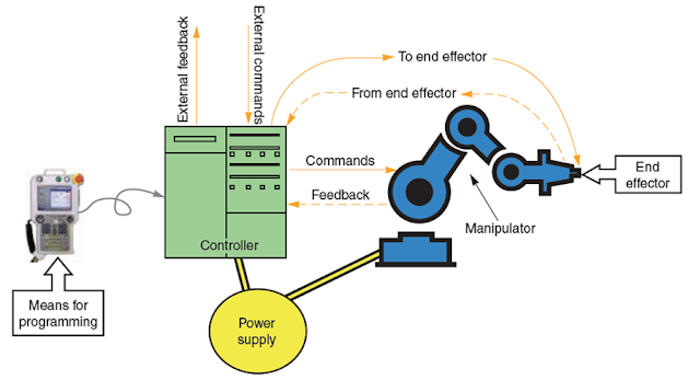
Robot Anatomy
The manipulator or robotic arm has many similarities to the human body. The mechanical structure of a robot is like a skeleton in the human body. The robot anatomy is, therefore, the study of the skeleton of a robot, that is, the physical construction of the manipulator structure. The mechanical structure of a manipulator consists of rigid bodies which are connected by means of articulations, is segmented into an arm that ensures mobility and reachability. The rigid bodies and their articulations resemble the links and joints of a kinematic chain. A wrist is attached at the end of the arm that confers orientation, and an end-effector that performs the required task is attached to the wrist. Most manipulators are mounted on a base fastened to the floor or on the mobile platform of an Autonomous Guided Vehicle(AGV).
Two rigid binary links 1 and 2, each with two holes at the ends A, B, and C, D, respectively to connect with each other or to other links in free space. The connectivity of links can either series or parallel.
 |
| The base, arm, wrist, and end-effector forming the mechanical structure of a manipulator |
Links:
The mechanical structure of a robotic manipulator is a mechanism, whose members are rigid links or bars. A rigid link that can be connected, at most, with two other links is referred to as a binary link. There are other types of links are being used which have a provision to connect with more than two links each.
 |
| Two rigid binary links 1 and 2, each with two holes at the ends A, B, and C, D in free space |
Joints:
Two links are connected together by a joint. By putting a pin through holes B and C of links 1 and 2 an open kinematic chain is formed as shown below. The joint formed is called a pin joint also known as a revolute or rotary joint. The name was given based on the relative motion provided by that joint which is a rotational motion.
The robot's motion can be accomplished by means of powered joints. The links can be connected to form a serial chain or a parallel chain. Majority of Industrial robots are serial chains.
 |
| An open kinematic chain formed by joining two links |
DAY 6
Classification of Robots
The robots may be classified in the following two broad categories,- Classification by coordinate system and
- Classification by control system
Classification by Co-ordinate system:
Industrial robots are available in a wide variety of sizes, shapes, and physical configurations. These configurations majorly depend on the robot arm or End-effectors reachability in the space. The part of the space in which the robot can execute its work is called as a workspace, work volume or work envelope. The vast majority of today’s commercially available robots possess one of the basic configurations:- Polar configuration
- Cylindrical configuration
- Cartesian coordinate configurable
- Jointed-arm configuration
Polar configuration:
 |
| Polar Configuration with Spherical workspace |
 |
| Cylindrical Configuration with workspace |
Cylindrical Configuration:
The cylindrical configuration, as shown in the figure, uses a vertical column and a slide that can be moved up or down along the column. The robot arm is attached to the slide so that it can be moved radially with respect to the column. By routing the column, the robot is capable of achieving a workspace that approximates a cylinder.
Cartesian Configuration:
 |
| Cartesian Configuration with box workspace |
Jointed-arm Configuration:
 |
| jointed arm configuration with spherical workspace |
The jointed-arm robot is pictured in Figure. Its configuration is similar to that of the human arm. It is sometimes called as an Articulated arm or anthropomorphic due to the structure. It consists of two straight components. Corresponding to the human forearm and upper arm, mounted on a vertical pedestal. These components are connected by two rotary joints corresponding to the shoulder and elbow. These two links are mounted on a verticle rotating table corresponding to the human waist.
DAY 7
Classification by control system
In order to operate, a robot must have a means of controlling its drive system to properly regulate its motions. With respect to robotics, the motion control system used to control the movement of the end-effector or tool.
- Limited sequence robots (Non-servo)
- Playback robots with point to point (servo)
- Playback robots with continuous path control,
- Intelligent Robots.
Limited sequence Robots (Non-servo):
Limited sequence robots do not give servo controlled to inclined relative positions of the joints, instead, they are controlled by setting limit switches & are mechanical stops. There is generally no feedback associated with a limited sequence robot to indicate that the desired position, has been achieved. Generally, this type of robots involves simple motion as pick & place operations.
Point to point motion (Servo):
These type robots are capable of controlling velocity acceleration & path of motion, from the beginning to the end of the path. It uses complex control programs, PLC’s (programmable logic controller’s) computers to control the motion.
The point to point control motion robot is capable of performing a motion cycle that consists of a series of desired point location. The robot is tough & recorded, unit.
Ex: Soldering, Spot Welding, Drilling etc.
Continuous path motion:
In this robots are capable of performing motion cycle in which the path followed by the robot is controlled. The robot moves through a series of closely spaced points which describes the desired path.
Ex:- Spray painting, arc welding & complicate assembly operations.
Intelligent robots:
This type of robots have not only programmable motion cycle but can also interact with its environment. It can make logical decisions based on sensor data received from the operation.
These robots are usually programmed using an English like symbolic language not like a computer programing language.
Ex: Interactive humanoid Robots, Fire fighters, AGVs etc.
I’m not that much of a online reader to be honest but your sites really nice, keep it up! I'll go ahead and bookmark your site to come back later. All the best
ReplyDeletemechanical engineering edmonton
I have been following you from the beginning. Elevate your adhesive applications with our cutting-edge systems in the UK. We specialize in providing innovative solutions for precise and efficient adhesive dispensing across various industries. Our range of systems caters to diverse needs, from automated production lines to manual operations, ensuring optimal performance and reliability. With advanced technology and expert support, we empower businesses to streamline processes, reduce waste, and enhance product quality. Whether you require adhesive spraying, coating, or dosing, our comprehensive range of solutions has you covered. Experience the difference with our top-quality adhesive application systems and take your operations to the next level. Unlock the full potential of adhesive dispensing robot by clicking here to access our exclusive content, including how-to guides, FAQs, and customer testimonials.
ReplyDelete